

What is extensible reinforcement in a bridge abutment or MSE Wall? It sounds like we are trying to build with some stretchy rubbery product. However Inextensible reinforcement sounds more like it. Nice and strong, and it won’t stretch. Now is that the case?
The industry does not clearly define these terms
Herein lies the issue with using these terms extensible and inextensible without clarifying what they mean. If you have ever been confused you are not alone. Even the guidance documents we use for design are often inconclusive as to what is required. AASHTO does not define exactly what each term means although it classifies reinforcement into either extensible or inextensible, and the New Zealand bridge manual adds some guidance in that it refers to inextensible as “usually steel” and extensible as “usually geogrid” but does state later that “Inextensible (steel) reinforcement shall be used…” in certain applications.
This all plays on a preconceived notion that steel is fundamentally stronger than plastic, and a stiffer stronger product is automatically better.
So, while I see a great place for both steel and geogrid reinforcement my question is, can we define the terms better, define what is required with these terms, and clarify the perceptions they carry?
It is clear that steel reinforcement is very stiff, and when compared with typical strain rates of engineering soils it is practically inextensible. However, that is not automatically a good thing in MSE wall design as it is much stiffer than the soil itself, and may not allow soil strength to mobilise. This needs to be considered in design. Also geogrids can essentially be as stiff as you need for design by selecting an appropriate grade, and ever more so as we see the rise of high tenacity polyesters, poly vinyl alcohol grids and even poly aramids.
So, lets dive a bit deeper into this and look at the difference in the mobilisation of soil strength between the two types, its impact on strain shedding between layers of reinforcement, achieving the required strength at very low strain, and also degradation of the reinforcement.
Mobilising soil strength and reinforcement strength
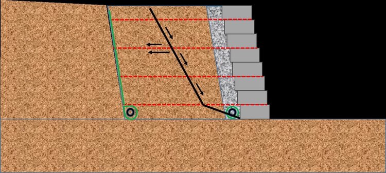
There is a fundamental difference in the way a reinforcement element interacts with soil between a truly inextensible element and one that will strain a small amount. Soil is a frictional material, that is it has some inherent strength in itself which we typically use to contribute to our stability calculations. Therefore, a small strain in the reinforcement at a critical point in the structure allows the soil itself to mobilise and the reinforcement to distribute load to the surrounding soil.
To quote from a recent FHWA publication “In reality, inextensible reinforcement restrains the formation of an active wedge and since the soil does not contribute its full strength, the reinforcement then must carry loads higher than extensible reinforcement to satisfy equilibrium of the wedge. While it may not be a problem meeting the needed strength of metallic reinforcement, its potential rupture after exceeding its yield strength could be incompatible with soil strength, thus requiring careful evaluation when considering inextensible reinforcement in LE analysis” 1
Strain shedding between layers of reinforcement
Given that geosynthetic reinforcement will strain a small amount and allow the soil strength to mobilise and contribute to the overall stability along any potential failure plane, we can see that there is the potential for load shedding, that is a given load can be redistributed to more than one layer of reinforcement. What we are seeing here is that the strain levels in geosynthetics can be managed, however they are more compatible with the strain levels in the soil itself than a truly rigid element.
Achieving the required strength at very low strain
While the strength of the reinforcement is a key design consideration, in some applications the strain of the reinforcement is also critical. Examples of this are walls with rigid facings where deformation will be detrimental to the structure, and reinforced soil structures supporting another structure such as a bridge or building. This is typically the main driver for authorities to insist on steel for the reasons given above.
However, while geosynthetic reinforcement can strain we can predict and limit this strain to practically any tolerance we require. The use of isochronous creep curves, which are generated to show strength versus strain in geosynthetic reinforcement at given temperatures over given time periods allows us to select a product and grade that will limit strain in the structure. This will typically be in the order of 1 – 2% depending on the code used for design, and referring to the above discussion, this allows some soil strength to mobilise, while limiting any deformation.
Also of great note and often overlooked is the fact that any strain in the reinforcement is only over the section or zone that is being stressed, which will not be the full length of the layer. For example, a 6m length of geogrid which is designed to strain no more than 2% will not move 120mm! The portion of the geogrid that is intercepting the critical plane and the resultant anchor lengths may only be a couple of metres or less, and only a small part of that under maximum load as the geogrid transfers load to the surrounding soil.
Degradation of the reinforcement
Reinforcement in bridge abutments typically needs to be able to maintain its design strength for 100 + years. With geosynthetic reinforcement there are a number of degradation mechanisms we must consider, the main ones being creep rupture, installation damage and environmental degradation, (primarily hydrolysis for PET grids and Oxidation for HDPE grids) All of these are well understood mechanisms and can be allowed for in design following globally accepted standards. The reductions to allow for these effects are significant, but well understood and readily calculated.
For steel reinforcement corrosion needs to be considered, including the effect of installation damage on any applied corrosion coatings for the same design life requirements. Likewise, this can be readily achieved so there is no specific degradation advantage for either type, unless for some specific site condition. An example may be a highly corrosive soil where steel may be less applicable.
Bringing it all together
Geosynthetic reinforcement has a long history of successful use in true bridge abutments even in high seismic areas. Of note is the Japanese Rail example where they have been using geosynthetic reinforced walls with rigid facings, both as true bridge abutments and also supporting the tracks for high speed trains for many years. These structures have performed exceptionally well and survived some serious earthquakes.
Is it not time we allowed strain limited geosynthetic design for our bridge abutments instead of requiring that they must have steel, and therefore limiting our options for true value engineering as the industry pushes on to new heights of research and experience.
Reference
1. Limit Equilibrium Design Framework for MSE Structures with Extensible reinforcement. FHWA-HIF-17-004 October 2016.
At Cirtex, we aim to reach the very highest in industry standards, both in safety and customer satisfaction. If you have any questions about us, our history, safety records or anything else that we do, please don’t hesitate to contact us. Our friendly and experienced staff will be happy to help in any way they can.