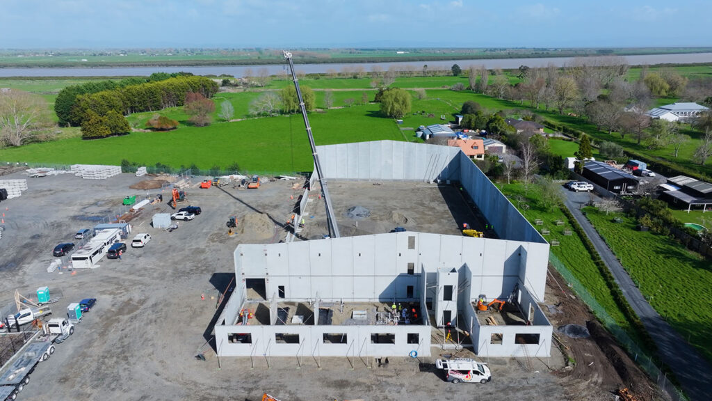
In this blog, we’re going to examine why Raft Foundations are a cost-effective option when building a solid footing, depending on the soil and site conditions. We’ll use the newly constructed Cirtex warehouse facility near Thames as an example, which has variable loading across the footprint from machinery, plant and offices.
Ground Conditions – Why a Geogrid Reinforced Raft?
As is always the case at the start of the design process for any load bearing structure, the key question the Geotechnical and Structural Designers face is “can we use the most economical footing possible?” This is usually a simple, shallow, spread footing. When the answer to this question is in the negative, the cost of the footings rise as options like ground improvement and piles come into play.
The Cirtex site location is a low-lying alluvial zone with a high groundwater table. Ground conditions consisted of loose to medium dense sands and silts down to at least 9mBGL. Liquefaction was a significant problem, with total reconsolidation settlements of up to 300mm predicted to occur.
Given this level of liquefaction settlement, the designers required a foundation system that would protect the structure’s footings from two potentially damaging conditions:
- A liquefied bearing capacity failure where footings such as pads and/or strips “punch” through a non-liquefied crust into compromised lower liquefied layers. With the potential to be “runaway” and uncontrollable, such failures can be serious.
- High, local differential settlements affecting adjacent footings.
A geogrid reinforced raft presented an option ideally suited to manage the above two conditions.
Geogrid Reinforced Raft – Format and Design Process
The design process for the geogrid reinforced raft involved significant liaison between the Geotechnical and Structural Designers. Both static and liquefied cases were of interest, as was the contrast in the results with and without the raft. The latter having been confirmed unacceptable, the former was then checked. It was found that the geogrid reinforced raft provided acceptable structural performance. As such, there was now no need to consider more expensive solutions such as deeper ground improvement or piling.
The key format points of the geogrid raft adopted are as follows.
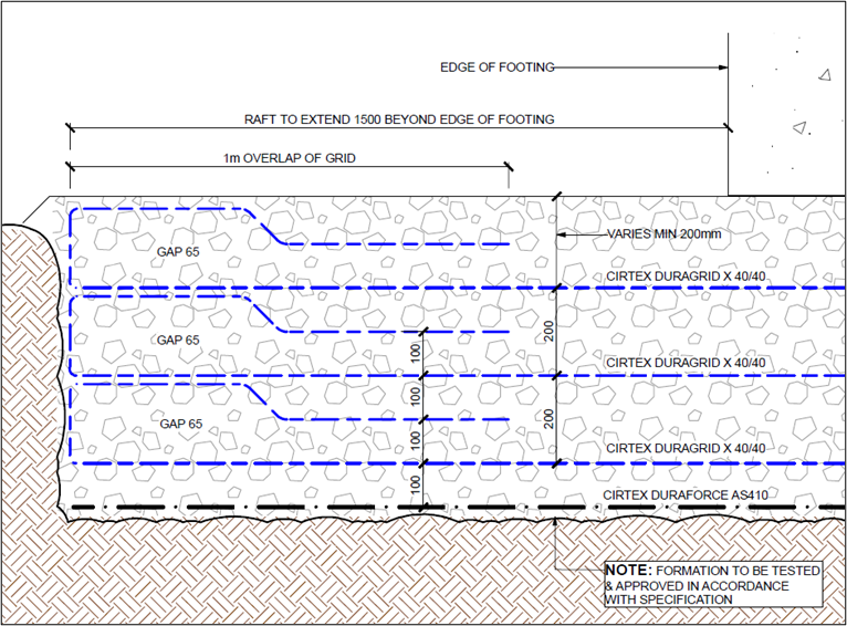
- A single layer of DuraForce AS410 is laid at the base of the excavation
- There are three layers of DuraGrid X 40/40 biaxial geogrid at a vertical spacing of 200mm
- A GAP65 well graded granular fill is placed & compacted between the geogrids
- A “wrap around” detail extending 1m beyond the building footprint was adopted

Raft Construction
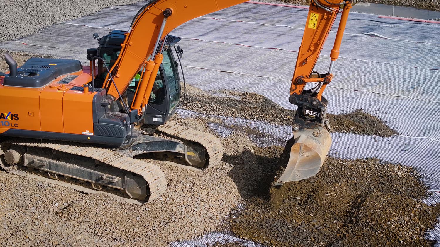
Any soft spots or zones of unsuitable material within the exposed raft formation were excavated away and replaced with the same granular fill as placed between the geogrids. With all formation soft spots treated, raft construction then advanced, with a layer of DuraForce and the first layer of DuraGrid being placed.
Ideally, the fill used between the geogrids is angular in nature. On this project, the parent material for the fill was Greywacke, with the lab tests returning a Maximum Dry Density of 2.2T/m3. As each fill layer was placed, compacted density tests were performed at the rate defined by the Specification. A Nuclear Density Gauge was used with tests being carried out using the Back Scatter and Direct Transmission modes. For each layer, an acceptable level of compaction was required before subsequent layers could be placed.

Site Supervision and the Finished Product
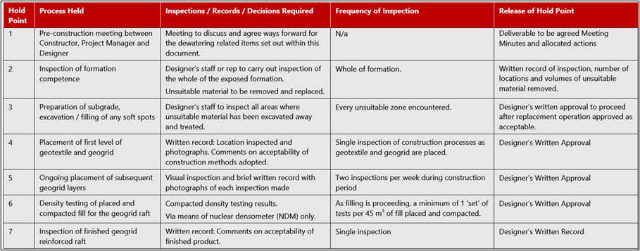
To provide a Producer Statement No.4 for the works, the observation and completion of various Hold Points was required. These Hold Points were defined in the Specification and reproduced on the For Construction drawings for ease of reference. These Hold Points are shown in the table below. It is their observance during the construction phase which allows the geotechnical designer to issue a Producer Statement No.4. With the Hold Points completed, Cirtex’s geotechnical designer was able to issue a PS4 for the raft construction. This certification is used by the local authority’s Consent Officer as proof of compliance with the NZ Building Code.

A geogrid reinforced raft can be a cost-effective solution to the bearing and settlement problems faced on sites where liquefiable soils are a problem. This summary has demonstrated how such a solution was chosen, designed and constructed using three layers of DuraGrid X 40/40 biaxial geogrid. With the geogrid reinforced raft having been completed to the satisfaction of the geotechnical designer, the commencement of the warehouse construction was able to begin.


